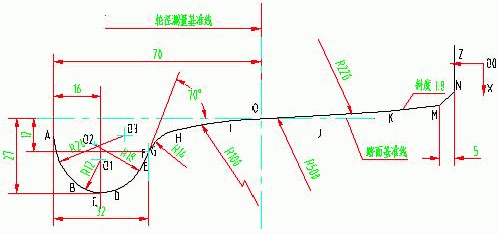
For a long time, most of the equipment used in the railway system to repair the van wheels was the C8011B wheel lathe produced by a heavy machine tool factory in the 1980s and 1990s. The lathe has two tool holders, each with two The coordinate axes (X-axis and Z-axis) are processed by electronic profiling on the rim and tread of the train wheel pair. The shape of the tread is shown in Figure 1:

figure 1
Since the machining method of the electronic profiling method is not high in precision, the processed rim tread shape is inferior. In addition, the operation control of the machine tool adopts the old-fashioned relay circuit control, the circuit is complicated, and the failure rate is high, which brings certain difficulties to the maintenance. With the development of China's railway industry, in order to adapt to the need of speeding up the railway and developing high-speed trains, the manufacturing precision and repair standards of the wheel rim tread are getting higher and higher, and the original method of processing the wheels with the profiling method is far from being able to To meet the accuracy requirements, the numerical control transformation of the machine tool is the most economical and effective way to meet this requirement. In the past two years, various railway depots and wheel factories have carried out numerical control transformation on their original C8011B wheel lathes. We used Siemens' 802S and 802C in the process of transforming the machine using Siemens' 802 series CNC system. 802D numerical control system, in which the equipment transformation scheme using 802D numerical control system is more typical.
When selecting the transformation plan of the equipment, the first thing to consider is to meet several requirements for the transformation: 1. The control of the X-axis and Z-axis of the tool holder is controlled by the original copy control and the digital axis. 2. Change all motion control of the original machine tool from the original relay circuit control to PLC control. 3. The shape of the tread after cutting meets the accuracy requirements, and the operation is as simple as possible.
In order to meet the above conditions, we chose Siemens' 802D CNC system, which is a digital CNC system introduced by Siemens in recent years. Its lathe version comes with a PP72/48 template, which can realize 72 points input and 48 points. The PLC control of the output, while the drive module is a two-axis power module, can have two linear axes and one spindle. The built-in speed feedback and displacement feedback sensor in the servo motor can form a semi-closed loop control system together with the host to achieve High machine accuracy. And the price is moderate, with high cost performance, can meet the requirements of equipment numerical control transformation.
Since the C8011B wheel lathe uses two tool holders to process the left and right treads of the train wheelset at the same time, we used two sets of 802D systems to control the movement of the left and right tool holders. All machine control of the machine is controlled by the PLC control unit of the left tool holder 802D system. The main hardware configuration of the left 802D system is:
1. PCU host 1 block 2, full-function vertical keyboard 1 block 3, PP72/48 template 1 block 4, 611UE drive power supply 5KW 1 block 5, 611UE dual-axis closed-loop control unit 1 block 6, 611UE dual-axis power module 1 block 7, 1FK6 motor 3000RPM18NM 2 8, external 2500P / rotary encoder 1 9, connecting cable and PROFIBUS data bus
The hardware configuration of the left and right systems is the same, using a SIMODRIVE611UE dual-axis control module to control the two servo motors to drive the X-axis tool holder and the Z-axis tool holder. The PLC unit of the right system only processes the PLC commands of the system itself. The MCP (Machine Control Panel) is integrated with the machine action button panel.
In the hardware configuration, we chose an external rotary encoder other than the standard configuration. The reasons for selection are as follows:
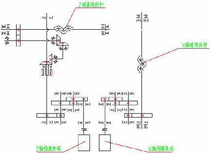
Due to the limitations of the numerical control transformation, although we replaced the original X-axis and Z-axis screw rods with ball screws, the middle transmission mechanism is still the old transmission mechanism, and the X-axis and Z-axis slides are driven by the servo motor. In the transmission process, the transmission structure of the X-axis and the Z-axis is shown in Figure 2:

figure 2
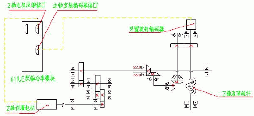
As can be seen from the above figure, for the X-axis, since the number of gear transmission stages is small, the transmission gap is not large, so the speed feedback and displacement feedback built into the servo motor can be used in the standard configuration. At this time, the movement accuracy of the X-axis slide is also Can meet the requirements. For the Z-axis, there are many transmission stages, and there are two-stage bevel gear transmission, so the transmission clearance is greatly increased. If we still use the displacement feedback of the servo motor end, then the Z-axis slide motion accuracy will not be obtained. Guarantee. Although there are many solutions, such as replacing the gear transmission or adding a grating ruler on the Z-axis guide rail, etc., it is not a good solution due to conditions and price. For this special case, in order to solve this problem, we finally considered the method of connecting an external rotary encoder to the Z-axis ball screw end. The connection method is shown in Figure 3.

image 3
At this time, the displacement feedback signal of the Z-axis directly detects the displacement signal of the Z-axis ball screw end, and the transmission gap of the gear transmission between the motor and the ball screw is included in the closed-loop chain, so the movement accuracy of the Z-axis slide table It has been greatly improved to meet the accuracy requirements.
However, in the drive configuration of the 802D system, the control interface of the linear axis does not have a special encoder interface like the 802S or 802C system. It has only two X412 and X411 interfaces that receive the motor feedback signal. How to connect the signals of the external encoder of the Z axis at this time? On the 611UE dual-axis closed-loop control unit, we see that there is an X472 interface, which is used to receive the encoder signal of the spindle. In our CNC transformation, the spindle control is not used, so the internal parameters of the system are modified. Then we can use this interface to accept the external encoder feedback signal of the Z axis. After connecting the connection cable of the external encoder as shown in Figure 3, we only need to modify the system data inside the 802D system and the drive data in the dual-axis power module to shield the displacement feedback signal built into the Z-axis servo motor and use an external encoder. The feedback signal is fine.
The method of installing an external encoder on the ball screw end is convenient to install, and the added cost is not much, but the use effect is very good, so the cost performance is extremely high. It is only necessary to carefully set the relevant machine data during the installation and commissioning process.
For the modification of the relay control circuit of the original machine tool, although the machine tool movement is not many, the control is more complicated, and the safety interlock between the movements is more. Therefore, the circuit in the original electric cabinet is very complicated, and all of them are replaced by 802D. After the control of the PLC unit of the system, the external control circuit is greatly simplified. The PP72/48 template in the standard configuration of the 802D system can provide 72-bit input points and 48-bit output points. The input and output points are sufficient for machine tools, and there is no need to add additional I/O input/output point modules like other CNC systems.
In the preparation of the NC machining program, 802D uses the G code programming common to the CNC system. The program is simple, in the programming of the machine tool, because the precision of the processed tread shape is high, and the user has put forward high requirements for the simplicity of operation, so we specially consider this in the preparation of the program. . As shown in Figure 1, the operator uses the diameter measurement when machining the wheel pair. In general, the tool in the X-axis direction during the machining of the lathe is programmed by relative coordinates or by setting the machine. The workpiece coordinates are processed by zero offset, but they are not suitable for this machine. In order to simplify the operation, we use the R parameter in the Siemens system to set the cutting amount. After programming the corresponding R parameter in the program, the operator only needs to input the wheel diameter value to be processed in the R parameter during machining. Then the program automatically converts the amount of cutting and cutting, which greatly facilitates the operation.
In addition, due to the stricter requirements on the size of the left and right wheel diameters after machining, the difference between the left and right wheel diameters after machining cannot be greater than 0.5 mm. Therefore we set an initial tool setting parameter in the R parameter to adjust the cutting reference. When the length of the tool holder or the reference point of the CNC system changes, the reference can be modified very quickly and conveniently, so that the input diameter value and the actual cut wheel diameter value are exactly the same.
Another point is that when cutting the wheel set, for other CNC systems, the Z-axis direction usually requires the operator to input the current coordinate value of the Z-axis into the parameter after facing the knife on the inside, while the current coordinate can be read in the 802D CNC system. The value function allows the operator to input data. We only need to add “R0=$AA-IM[Z]†to the machining program, and the system can directly read the current Z-axis coordinate value into R0 of the R parameter. In this way, the operator only needs to input the wheel diameter value of each pair of wheels to be processed, which is very simple and convenient.
In the process of numerical control transformation of a device, the electromagnetic interference phenomenon has always been a big problem that often plagues the debugging personnel in the installation and commissioning site. Because the workshop and the site using the old equipment generally have a bad working environment, the strong interference source is more. Moreover, the voltage fluctuation of the power grid is large, and the quality of the neutral line and the ground line is not very high, so the interference phenomenon is often encountered during the debugging process. In order to eliminate interference, design and debuggers have to pay a lot of extra effort. For example, we encountered the following situation in a wheel lathe that uses other systems for numerically modified: the CNC system works normally, but there are always one or two CNC systems that suddenly stop suddenly during operation, and the screen displays the alarm as X-axis code. The hardware of the device is faulty. After the power is turned back on, the machine tool returns to normal. We are beginning to suspect that the displacement encoder is damaged or the line is in poor contact. However, after checking for a long time, many measures have not been taken to eliminate this phenomenon. The final inspection result determined that the system was disturbed by the instantaneous fluctuation of the shop voltage. Later, a voltage regulator transformer had to be installed at the incoming end of the equipment power supply, and a good quality ground wire was installed separately. Although the problem was finally solved, a lot of time and effort was wasted. After adopting the 802D system of Siemens, the system adopts the communication mode that connects the various functional modules with the Profibus data bus, so the structure is simple, and the anti-interference is greatly increased, which reduces the electromagnetic interference of the numerical control equipment. The possibility of various unknown fault phenomena.
After we have numerically modified the C8011B wheel lathe of many units of the railway system with Siemens' 802D numerical control system, the modified machine tool has reliable performance, high processing precision, simple operation and convenient maintenance, so it has been widely recognized and highly accepted by users. Evaluation.
Sanitary Pipe Fittings Series,Sanitary Pipe Fittings,Sanitary Stainless Steel Elbow,Sanitary Stainless Steel Pipe Fittings
WENZHOU FOREVER CLASSIC TECHNOLOGY CO.,LTD , https://www.fballvalve.com