Titanium is an important structural metal developed in the 1950s. Titanium alloy has become the most important structural part of the aircraft due to its light weight, high strength, high impact toughness, good mechanical properties and good corrosion resistance. Ideal materials, mainly used in aviation, aerospace, military, medical, petroleum and other fields. However, due to the poor machinability of titanium alloys, its wide application has been severely restricted for a long time. With the rapid development of the aviation industry, the processing of titanium alloy aviation products as an emerging, high value-added industry is in the stage of vigorous development.
Intersection joint parts have typical thin wall, multi-cavity, inclined angle, normal hole and so on, as shown in Figure 1. The intersection joint is the connecting structure of the aircraft wing and the engine, and it is a key important part. The material used for the product is TC21 high-strength titanium alloy. TC21 titanium alloy is one of the five characteristics of high strength, high toughness, high modulus of elasticity, excellent welding performance and high damage tolerance. It is a high strength, high toughness damage tolerance type titanium alloy independently developed by China. At present, the research on this material at home and abroad is mainly concentrated in the fields of material physics, material mechanics, chemical properties, etc., and research on mechanical processing is rarely seen in the world.

Figure 1 Typical intersection joint parts
For the thin-walled, multi-cavity, and inclined corner structures of the joint joint parts, the processing difficulty lies in the treatment of the corner position. The traditional machining method is based on Z-axis layered cutting, but the disadvantages of Z-axis layered cutting are also obvious. First of all, the processing efficiency is relatively low, and the material removal rate is small. Secondly, due to the long tool overhang, the machining process will cause the knife to be undercut. Again, the tool cannot withstand the titanium alloy due to the large aspect ratio of the tool. Large radial anti-cutting forces result in turbulent overcutting and even tool breakage.
1. Milling and milling finishing
The plunge milling method is also called Z-axis milling method. The principle is that the tool continuously moves up and down in the axial direction to quickly remove the workpiece to be processed. It is suitable for high-efficiency roughing of large cutting amount, and it is also difficult to process other processing methods. Finishing of the corner of the side wall. Figure 2 shows the sidewall corner dimensions of titanium alloy aerospace products. The use of plunge milling has the following advantages:
(1) Reducing the deformation of the workpiece The typical wall thickness of the joint parts is 5mm, while the TC21 material has the characteristics of high elastic modulus, and the deformation control is a priority of the processing technology. The practical data shows that the deformation of the part 1000mm length is about 0.35mm, and it shows an amplification trend. By applying the plunge milling method to remove the sidewall corner allowance, the cutting force acting on the workpiece is greatly reduced, so that the subsequent corner fine insertion and overall finishing become efficient and light, and the workpiece deformation is reduced, thereby improving the manufacturing precision.
(2) Reducing the radial cutting force acting on the milling machine TC21 The material has a hardness of about 390 HB and a strength of about 1200 MPa, which requires extremely high spindle torque for the processing equipment. By applying the plunge milling method, the radial wear of the machine tool spindle can be reduced. At the same time, since the aeronautical products are mostly five-axis machining, the plunge milling method can also reduce the radial force of the fourth and fifth rotary drive shafts of the machine tool. Precision inserting the corners of the wall allows the corners to be fully finished in place and to improve the surface quality of the workpiece.
(3) The tool overhang elongation is larger and the tool loss is smaller. Because the force of the plunge milling method on the tool is concentrated on the tool axis, the radial cutting force of the plunge milling process is greatly reduced, so compared with the side milling process, The milling method basically eliminates the radial vibration of the tool and has higher processing stability, so that the tool can be extended more deeply and the machining depth is deeper. Tests have shown that with reasonable parameters, the titanium alloy tool can achieve 6 times the tool diameter (length to diameter ratio of 6:1) or more by using the plunge milling method, and the tool loss and breaking rate are also greatly reduced.
(4) Improve processing efficiency Titanium alloy is a difficult material to be processed, and the side wall corner (see Figure 2) is processed using traditional layer-down side milling. The production efficiency is very low, which is difficult to control due to factors such as tool length, machine tool strength, and workpiece rigidity. Achieve efficient processing. The plunge milling method solves this series of problems well and more than doubles the processing efficiency of manufacturing.
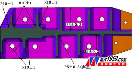
Figure 2 part side wall corner
In general, the use of the plunge milling method for finishing the sidewall corners can solve the two technical problems of difficult cutting and difficult corner machining of titanium materials.
2. CATIA-based programming method
At present, the mainstream CAM system basically supports the milling and milling programming commands. The specific methods and methods have their own advantages, and the processing effect is also different. The following is an example of the aeronautical industry general software CATIA. Introduction.
(1) Preparation process After starting the CATIA software, select “Start†→ “Processing†→ “Advanced Processingâ€, and set the corresponding 5-axis machine tool, machining coordinate system and machining in the pop-up part processing action dialog box (see Figure 3). And pre-set items such as simulation geometry, simulation blanks, safety planes, etc.

Figure 3 part processing action settings
After completing the setting of the part machining action, the tool path of the roughing and semi-finishing of the workpiece is completed. At the same time, in order to eliminate the problem of “drilling and milling†in the plunge milling process (that is, the entire tool diameter is completely drilled into the workpiece). It is strictly forbidden in the plunge milling process. Before the corner of the side wall is finely inserted, the path of the workpiece web surface finishing is also required to achieve the surface of the web surface as shown in Figure 4. Part status.

Figure 4 Part status before plunge milling
(2) Side wall corner semi-finishing process Semi-finishing side wall corners are inserted into the web surface from the top to the bottom using the “point position†plunge milling method, and the entire corner allowance can be removed with high efficiency by simply inserting a knife.
As shown in Figure 5, select “Insert†→ “Machine Action†→ “Surface Machining Action†→ “Plug Millingâ€, and set in the pop-up plunge dialog box (see Figure 6): 1 part body primitive, 2 upper limit diagram Yuan, 3 check primitives, 4 lower limit primitives; set semi-finishing "bottom offset" to 0mm, "side offset" to 0.5mm, and "check surface reserve" to 0.5mm.

Figure 5 plunge milling action settings

Figure 6 plunge milling dialog
Set the machining tool (see Figure 7), the side wall angle is R10, and the bottom angle is R5. Therefore, the tool uses φ20R5 4-blade solid carbide coated milling cutter.
Set the machining advance and retract mode (see Figure 8), the feed is set to 5mm corner axial feed, and the retraction is set to 5mm base angle normal retraction.

Figure 7 tool settings

Figure 8 forward and backward knife settings
In the "Machine" dialog box (see Figure 9) set: 1 grid line form is selected as "point" mode; 2 select the machining point as the corner center point; 3 select the tool axis direction as the corner axis; 4 set the machining accuracy to 0.02 Mm, the minimum insertion length is 0mm.
In the "Axis" dialog box (see Figure 10), the distance values ​​for each axial machining during the machining process are set in turn according to the actual situation of the workpiece blank.

Figure 9 processing point setting

Figure 10 machining process axial distance setting
After the above steps are completed, the path of the semi-finishing tool for the side wall angle of the plunge milling is calculated.
(3) Side wall corner finishing process Finishing side wall corners are offset offset along the corner contour using “offset†plunge milling to improve workpiece dimensional accuracy and surface quality.
In the "Machine" dialog box (see Figure 11) set: 1 grid line form select "byoffset", 2 select machining contour as corner contour, 3 select tool axis direction as corner axis, 4 set machining interval is 0.5mm The horizontal interval is 0.25mm. 5 Click “showpoints†to view the plunge points to be generated, and finally confirm whether the plunge points to be generated meet the requirements.
The settings for the geometry of the side wall corner finishing, the tool, the advance and retraction, etc. are the same as those for each item in Section 3.2 of this paper. In addition, the distance value of each axial machining in the machining process needs to be set in the "Grid Line" dialog box, and finally the tool path is generated as shown in Fig. 12.

Figure 11 sets the offset processing

Figure 12 generates the plunge cutter path
The CATIA system-based milling tool path preparation method is simple and intuitive, with rich processing methods and powerful forward and backward knife functions. The procedures compiled by the CATIA system have proved that the processing process is stable and the processing quality is excellent.
3. Cutting parameters
Since the cutting mechanism and general milling differ greatly in the cutting mechanism, a systematic study of the machining parameters is required.
(1) Tool selection Compared with the ordinary machining method, the plunge milling process puts higher requirements on the tool, not only requires good rigidity and high precision, but also requires stable machining process, high durability, good chip breaking and chip discharging performance. At the same time, refuse to use material tools that are easy to produce affinity with titanium.
Titanium alloy side wall corner milling has the following requirements: 1 The plunge cutting tool should use multi-blade unequal distance milling cutter with ultra-fine grained carbide substrate and high temperature resistant coating. The cutting edge is sharp and the chip removal is smooth. The vibration is extremely low. 2 The length of the semi-finished milling cutter R should be equal to the minimum radius of curvature R min of the contour surface of the part sidewall to improve the cutting efficiency. 3 The length of the plunging and finishing milling cutter R should be less than or equal to the minimum radius of curvature R min of the inner contour surface of the part to improve the cutting accuracy. 4 Plunge milling semi-finishing, finishing milling cutter bottom angle R d should be equal to the maximum radius of curvature R max of the bottom contour surface of the part. 5 The length of the plunge cutter should be shortened as much as possible to ensure that the knife has sufficient rigidity. 6 The tool needs to have an internal cooling function. In combination with a cutting fluid that does not contain chlorine or other halogen elements and contains no sulfur, the tool needs to be cooled internally and externally.
(2) Tooling Titanium alloy processing is a high-strength cutting process, and the clamping requirements for the tool are stable and high. It is recommended to use a thermal expansion handle clamp when conditions permit, or to use a high-precision, powerful grip to clamp the tool.
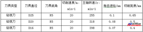
(3) Cutting amount After repeated experiments on the spot, our company has established the processing parameters suitable for the corner milling and milling of titanium alloy (see attached table), which has been applied to actual production.
Plunge cutting table
4. Conclusion
In this paper, through a series of researches on the side-turn corner milling process, programming and cutting parameters of titanium alloy, the application of titanium alloy plunge milling is discussed in detail, and it has been verified by many rigorous experiments and batch production. It proves that the insert milling method for finishing the sidewall corner of titanium alloy aviation products has excellent processing effect. Figure 13 shows the simulation effect diagram and actual machining effect of the side-turning and milling of the titanium alloy. The research in this paper has a systematic reference value for the efficient processing of titanium alloy. The author hopes to play a certain role in promoting the CNC machining of China's aviation components.

Figure 13 Plunge milling effect
Indoor Par Light,Mini Par Led,Led Zoom Par Light,Led Flat Par Light
EV LIGHT Guangzhou Co., Ltd , https://www.evlightpro.com