In order to greatly reduce costs and make remote digital video audio monitoring applications more popular, the current development trend at home and abroad is to use embedded systems. That is, a dedicated microprocessor, a digital chip for image and sound, a data compression chip, and a network interface chip are used to develop a minimum application single board system according to specific functional requirements. In this way, there is no waste of system functions, which can greatly reduce costs. Moreover, since the software is solidified in the Flash ROM in the board, the system is more reliable.
1 Overview of the overall structure and function of the system
Since the embedded system has all the above advantages, the author has recently developed a multimedia remote monitoring and management system based on embedded technology.
The system adopts the current popular TCP/IP network protocol, and the video coding is based on the H.263 protocol--low bit rate video communication coding algorithm 音频 audio coding based on G.723 protocol--low bit rate audio communication coding algorithm. They can transmit images and sound in environments with low network bandwidth and even on telephone lines.
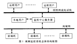
The whole system is mainly composed of three parts: front-end machine, monitoring center and client. The specific structure is shown in Figure 1.
 |
The front-end machine is a printed circuit board of an embedded system. Its main functions are as follows:
· Four analog video signal inputs, which can be arbitrarily selected for sampling and compression coding;
· Encoding and decoding of an audio signal;
· transmitting video encoded data and audio encoded data to the monitoring center via a local area network, and receiving audio encoded data transmitted by the monitoring center;
· Send control commands to the camera's pan/tilt controller via the RS-232 interface;
· Receive user alarm signals through the parallel port of EPLD and transmit to the monitoring center via LAN.
The monitoring center is the backbone of the entire video surveillance system. Its main functions are as follows:
· Send user control commands to the front-end machine through the LAN, such as the selection of the front-end machine, the selection of the video channel, and the adjustment of the image parameters, including the frame rate, the size of the code traffic, the chroma, the brightness, the saturation and the contrast, and the sound encoding volume. Size, etc.
· Receive the video encoded data of the multi-channel front-end machine, save it on the local hard disk, decode at the same time, and display the multi-channel decoded image;
• Forward current video encoded data to remote users, or transfer saved image data.
The client is an interface that provides a user action. Local users can use it directly on the server in the monitoring center; remote users have another set of operating interfaces that can use fewer functions than local users, but it allows remote users to obtain local video information over the Internet or telephone lines.
The system also has very good scalability. For large monitoring sites with hundreds or even thousands of monitoring points, multi-level cascading can be adopted, that is, between the front-end machine and the monitoring center, plus one or more level regional servers, each regional server can manage ten From a few to dozens of monitoring points, they share the work of the monitoring center and are controlled by the monitoring center.
2 front-end hardware design and function of each module
The hardware development work of this embedded video surveillance system is mainly focused on the hardware design and debugging of the embedded front-end machine.
The front-end machine is an embedded system, and the hardware structure is relatively complicated. The overall structure is shown in Figure 2. Mainly includes embedded CPU, EPLD, video analog-to-digital conversion chip, video compression coding chip, audio codec chip, audio analog-to-digital and digital-to-analog conversion chip, Ethernet controller, data buffer memory, network transceiver, Flash ROM, RAM , a variety of power chips and clock chips. These chips are combined according to their respective functions, which constitute several modules: CPU module, power clock module, control module, video acquisition and coding module, audio acquisition codec and analog input and output module and network module.
 |
The CPU module is the core of all hardware modules, including embedded CPU chips, two RAMs and two Flash ROMs. A flash ROM stores the entire hardware monitoring system, also called ROM Monitor. When the system is powered on, the CPU transfers the program from it to perform self-test and initial configuration of the entire system hardware, and provides a simple operating environment for the user. When the system fails, it can be used to read the status of the main register of the CPU to find out the cause of the fault. Another piece of Flash ROM is used to store the user's application. When the entire system passes the self-test, the CPU reads the user's application into RAM and executes it. The CPU connects to the video compression coding chip and the Ethernet controller through the PCI bus, and performs scheduling and data transmission and reception. The CPU also provides two serial ports, one of which is connected to the serial port of the ordinary computer. Through the HyperTerminal under Windows, the user can monitor and debug the entire system; the other serial port is used to control the camera head.
The power clock module is responsible for providing clock and power to the entire system and is the basic module of the system. Because the entire embedded system uses more chips and devices, and each device has different power and clock requirements, the design uses four power chips and six clock crystals. Considering the existence of multiple power supplies, the power layer is divided into seven blocks to supply power to the required devices. At the same time, the digital ground and analog ground are also segmented. This achieves a higher quality of the power signal of the entire system, greatly improving the stability and reliability of the device operation.
The control module is a programmable logic chip EPLD. Its main functions include address decoding and chip selection of PCI bus, power control, CPU reset, I/O input and output, and watchdog logic. Among them, 8 I/O inputs are used as user alarm inputs, and 6 I/O outputs show the operating status of the system. Watchdog logic is an indispensable part of embedded systems. Because the embedded system generally does not need to be supervised at all times, when an accidental abnormal situation such as a crash occurs in the working state of the system, the watchdog can automatically reset the entire system to restore the system to a normal working state. The video acquisition and coding module is mainly composed of a video analog-digital conversion chip, a video compression coding chip and a RAM. The main function of this module is to send the analog video input to the video analog-to-digital conversion chip for analog-to-digital conversion, and send the transformed digital video data to the video compression coding chip. The video compression coding chip compresses and encodes the video data in RAM. Finally, the video encoded data is sent to the CPU through the PCI bus. In addition, the video compression coding chip can also control the image parameters of the video analog-to-digital conversion chip through the I2C bus, including the brightness, chrominance, contrast and saturation adjustment of the image, and the selection of the video sampling channel.
The audio codec module mainly includes an audio codec chip, an audio modulus and digital to analog conversion chip, and an audio analog signal processing circuit. The audio analog signal processing circuit mainly filters and amplifies the audio signal; the function of the audio analog-digital and digital-to-analog conversion chip is to convert the analog audio signal into a digital audio signal and convert the digital audio signal into an analog audio signal; the audio codec chip The main function is to encode and decode digital audio signals.
The network module is mainly composed of an Ethernet controller, a data buffer memory, a network transceiver, and an EEPROM. It is a bridge between the CPU and the network, similar to a network card on a computer. It supports the IEEE Ethernet physical layer protocol. In EEPROM, users can burn the underlying hardware î—¤ MAC î—¥ address of the embedded system.
3 Software Development
The software of this system is mainly divided into three parts: embedded front-end machine program design, monitoring center software design and user interface design.
3.1 Software design of embedded front-end machine
Due to the characteristics of the monitoring system, the front-end machine must meet the requirements of real-time and concurrency, so the application software is based on the embedded real-time operating system. The SuperTask embedded real-time operating system developed by US Software is adopted. It has small kernel, user configurable system parameters, efficient multi-tasking management, support for priority queuing and round-robin scheduling, support for multiple physical media and standards, complete TCP/IP network protocol stack, compatibility with BSD, and full compliance. Features such as the ANSI C standard.
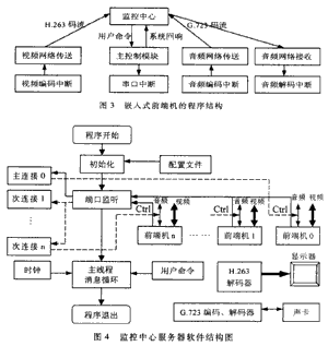
The application of the front-end machine consists of several tasks such as main control, video coding interruption, video network transmission, audio coding interruption, audio network transmission, audio network reception, audio decoding interruption and serial port interruption. The association of each task is shown in Figure 3. .
 |
3.2 Software design of the monitoring center server
The monitoring center server software is developed with VC++ under Window2000, and its overall structure is shown in Figure 4. First, the program will be initialized according to the system parameters of the configuration file. These system parameters can be modified in the configuration file according to their needs.
Then, the program will perform port listening, and CCtrlListenSocket will start working as a Socket of the monitoring center server. Once the front-end machine requests the control port to connect to the monitoring center, first assign the connection to CCtrlSocket through Accept, and then get the remote IP address through CCtrlSocketGetPeerNamerPeerAddressrPeerPort. If the address is illegal, it is immediately disconnected; if the address is valid, CCtrlSocketInit is called to initialize. The main thread mainly receives commands such as buttons from the user, and uses the timer to refresh the total time of the system operation and uses the timer to check the connection status of each front end machine.
3.3 User Interface Design
The user interface is developed using Delphi. Delphi is currently the most popular development language in the world. It is rich in application templates and comes with various tools to make the development of the user interface more convenient and more beautiful.
:
Internal Thread Cylindrical Pin,Alloy Steel Cylindrical Pin,Flat Head Cylindrical Pins,Polished Steel Cylindrical Pins
Qingdao Yukun Bearing Needle Roller Co.,Ltd. , https://www.ykneedleroller.com