At present, the distributed photovoltaic system grid-connected mode can be divided into three types of self-use self-utilization Internet access, full access to the Internet, and all self-use models. The former two modes are more common, and the user-side grid connection mode must be used for all private use in certain special regions. Type, that is, excess power is not allowed to reversely transmit power to a higher-level power grid through a low-voltage distribution transformer. In a grid-connected power generation system, the output of the photovoltaic array changes with the change in external irradiation and temperature in order to achieve anti-backflow. The effect of control can make the system match the load to consume power. The system needs to configure the anti-backflow controller to adjust the power generated by real-time monitoring of the current direction signal of the low-voltage side of the AC side. The principle of protection technology is briefly introduced and analyzed.
1. Basic principle of anti-backflow control device
The basic principle of anti-backflow control is to rely on the AC current transformer to collect the current direction signal feedback to the backflow prevention controller and control the energization or de-energization of the lead wires A1 and A2 at both ends of the contactor coil so that the contacts of the contactor act. , control the power output of the inverter we want to control. Under normal circumstances, A1 and A2 are connected in series to the control circuit, and the contactor pulls in. There is a certain voltage between A1 and A2. Figure 1 shows the schematic diagram of the simplest anti-backflow control in the AC power grid cabinet. The inverter has three Four-phase access, after the circuit breaker and the AC contactor, is connected to the input end of the copper bar, the left side of the copper bar is connected to the 380V power grid, and the output end of the copper bar is connected to the load end. A1 and A2 are two independent terminals of the AC contactor. Since the contactor coil is 220V, they are connected to the live and neutral wires of the power grid respectively, and the coils of the contactor are transmitted. Each of the three phase wires passes through a current transformer. The primary wiring of the transformer is marked with the P1 side facing up and the P2 side facing down. Looking from the left side of the schematic diagram to the right, the grid current flows to the load, and then the P1 side faces to the left. The P2 side faces right.
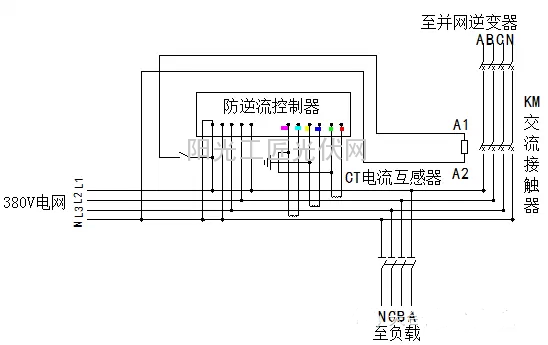
Figure 1 Basic principle of anti-backflow control
2. AC current transformer
AC current transformer in the role of anti-backflow system has two points, one is the measurement, the large current is converted into a small current measurement sampling. The second is to send a signal to the controller to disconnect or pull the contactor. Figure 2 is a physical diagram of a through-type AC transformer with a current ratio of 250/5A and a maximum output current of 5A.
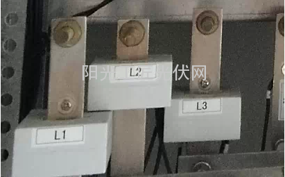
Figure 2 through-type current transformer physical map
The standard connection method of the penetrating current transformer is that the primary current passes through P1 (also called L1) and passes through P2 (also called L2). When the primary current flows from the P1 end of P1, the secondary current flows from S1 (also called K1). Outflow through the external circuit back to S2 (also known as K2), as shown in Figure 3. When the alternating current flows in the circuit, its direction changes periodically with time, but at a certain moment, the current terminal in the coil must have an inflow direction, and the other is the outflow direction, and the induced secondary current is also the same There is also the inflow and outflow of current, so the polarity of the current transformer is the relationship between the primary current direction and the secondary current direction. If one side of the primary side has the same polarity as one side of the secondary side, that is, it is positive at the same time, in the wiring, L1 and K1 are called the same polarity terminal, L2 and K2 are also the same polarity terminal, and the primary current is from L1 goes into L2 and is in the positive direction.
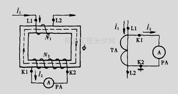
Fig. 3 Description of primary current, secondary current flow direction and terminal mark when the current transformer is connected
If the primary loop of the transformer is reversed, that is, the primary side L2 flows in and L1 flows out, even if the secondary connection is correct, the current direction is just the opposite. If the secondary loop of the transformer is reversed, the detected current is not Change, but relative to normal conditions, because the direction of the reference circuit is fixed, and the polarity of the measurement current is reversed from the normal one, the current flow will be reversed, and the phase will be 180 degrees out of phase, which will bring about the judgment band of anti-backflow control. To malfunction, that is to say that even if the photovoltaic power generation power is less than the power usage of the load, the backflow prevention controller will erroneously judge that there is a backflow in the system.
For example, when we use the current transformer to connect the current meter, the reversed power meter will reverse. The reason is that the power measurement inside the power meter needs to include the power factor, and the power factor is the cosine of the phase difference between voltage and current. Therefore, when the current phase is reversed, the current phase angle is 180 degrees different from the original, so that the phase difference between voltage and current is 180 degrees, resulting in a negative power output. If the transformer is connected one at a time, As long as the second S1 and S2 reversed on it.
3. Non-intelligent anti-backflow control process
“Technical Regulations for Photovoltaic Power Plant Access to Power Grids†requires that: When a photovoltaic power plant is designed to be irreversibly connected to the grid, reverse power protection equipment should be provided. When a reverse current exceeds 5% of the rated output, the photovoltaic power station should be stopped within 0.5-2 seconds. Power transmission to the grid. Take the 100kW rooftop PV project on the actual project as an example. The main feature of the system is the anti-backflow control in the AC power distribution cabinet. The control method is to directly operate the contactor to disconnect the photovoltaic side. When the PV generation power is greater than the load power, the PV Power Supply will Send it to the power grid, but at this time, once the reverse flow control detects that there is reverse power at the power grid, the anti-backflow controller sends a signal to the contactor, the contactor is automatically disconnected, and the inverter stops working because it is disconnected from the power grid. It is only supplied by the power grid, and at the same time, the time relay in the anti-backflow cabinet starts timing. For example, if the set time is 10 minutes, that is, after 10 minutes, the anti-backflow controller monitors the grid for any backflow. If there is no backflow, the contactor automatically pulls in and out. In the use of anti-backflow controller, the parameters need to be set in accordance with the norms, reverse current protection set range of 1% -20% continuously adjustable, with 1% = 0.05A as a benchmark, that is 1% = 0.05A, 20% = 1A, 5% is 0.25A. The maximum delay time of the controller is 2s, ie it needs to open the contactor within 2s. Therefore, the normal working conditions of the non-intelligent anti-backflow system are as follows: the contactor pulls in and does not disconnect, the inverter is not disconnected from the power grid, and the photovoltaic power generation power is always less than or equal to the load power.
4. The effect of non-intelligent anti-backflow control system on power generation
The basic principle of the non-intelligent anti-backflow control was mainly introduced above. Although it is relatively simple, it is difficult to coordinate the matching relationship between the solar cell module power generation amount and the load demand for a non-equilibrium daily electricity load, and it is difficult to satisfy the photovoltaic supply to the load. Continuity, and for daily electricity load balance, for example, a factory using refrigeration appliances and electric heating equipment, the demand for load power in summer and winter is more than in spring and autumn, if the system capacity is designed to meet the power demand in summer and winter, in spring and autumn It will inevitably generate excess electricity, and will be completely cut off by the anti-backflow control, which will lead to a huge waste of photovoltaic power generation. Therefore, some improvements need to be made for non-intelligent anti-backflow control. The current general approach is to use intelligent control. The method, through RS485 communication with the inverter, reduces the power output of the inverter and matches the load.
5. The principle of intelligent anti-backflow control system
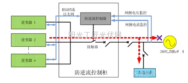
Figure 4 Intelligent anti-backflow control
Take the sunlight power ARP anti-backflow control cabinet as an example. The intelligent anti-backflow control generally has four parameters, namely: Pt: The measured power of the grid at the grid point, including the power provided by the grid to the load and the reverse power. Ps: Control power. Pr: Set reverse power value. Tr: set the maximum reverse power duration, Ts: reverse power recovery time [1].
When the grid-side power Pt is greater than Ps, the contactor is controlled to pull in, and a communication command is sent to the inverter to control the power of the inverter to gradually increase. When the grid-side power Pt is less than the set control power Ps but greater than the set Pr, the controller sends a communication command to the inverter to control the inverter power to gradually decrease until Pt=Ps; when Pt Taking a 100kW grid-connected system as an example to illustrate the control process, the system is equipped with 10 10kW inverters, assuming Ps=50kW, Pr=20kW; when the inverter is not put into use, the load requires 130kW, which is provided by the grid. The measured power at the grid point is 130kW; Pt>Ps, the control cabinet sends a signal, commands the inverter to be put into use, and reduces the supply of the grid to the load. After a total of 8 inputs, the system supplies 80kw and the grid supply is 50kW. At this time, Pt= Ps, the remaining 2 inverters cannot be put into operation. When the load changes, such as the load increased to 140kw, need to invest in an inverter; system supply 90kW, power grid 50kW; when the load 140kW reduced to 120kW, the grid is still supplying 50kw, the system supplies 90kW, the system more than 20kW, its power The flow direction is opposite to the flow direction of the power grid. After the power is superimposed, it becomes 30 kW, ie Pt=30 kW<Ps, but Pt>Pr. At this time, the controller orders to reduce the inverter, and after reducing 2 stations, Pt=Ps; when the load 140 kW is reduced to 110 kW The power grid still supplies 50kW, the system supplies 90kW, and the system has 40kW more. Its power flow is opposite to that of the power grid. After the power is superposed, it becomes 10kw, that is Pt=10kW<Pr. If the duration is T> Tr, the control cabinet orders the inverter to shut down the inverter. The specific process refers to Figure 5. 6. Summary The non-intelligent and intelligent anti-backflow control methods are briefly introduced in this paper. There is no doubt that the anti-backflow will bring about the loss of photovoltaic system power generation. The non-intelligent control methods are now rarely used, but for special countries or In areas and specific conditions, it is generally recommended to use intelligent anti-backflow control methods or to use energy storage systems under the premise of cost for system design and installation, which can maximize the utilization of photovoltaic power generation. Solar Light shadow wall light Solar light shadow wall light Dongguan XINYUDA Technology Co., Ltd. , https://www.gdxige.com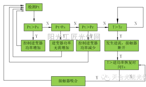
Figure 5 Intelligent anti-backflow control logic process