| Abstract: The connecting rod is one of the important components of the air compressor. It is subjected to a drastically changing dynamic load during the working process. This dynamic load is transmitted to the two connecting bolts and nuts of the connecting rod body and the connecting rod cover. Therefore, in addition to the higher technical requirements for bolts and nuts, higher requirements are placed on the holes in which the two power bolts are mounted. The 2V-6/8 air compressor connecting rod bolt hole produced by a factory has a length-to-diameter ratio of 6:1, which is a small deep hole. There are problems such as guiding, chip removal, cooling and lubrication during processing. The traditional process uses the process route of drilling, expanding and hinged, and working hard from the tool and tooling to meet the design accuracy requirements. This paper introduces in detail the machine tool modification, gun drilling structure and vibration drilling mechanism when machining deep holes with vibrating gun through production practice. |
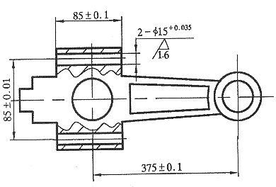 Figure 1 connecting rod |
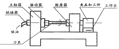 Figure 2 Overall layout of the gun drilling machine |
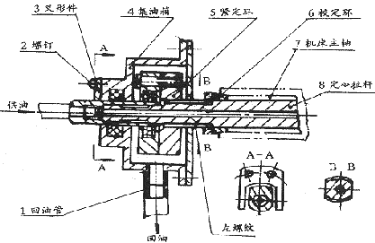 Figure 3 connector |
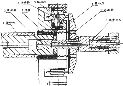 Figure 4 Drill chuck and vibration source |
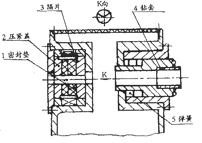 Figure 5 chip box |
 Figure 6 gun drill |
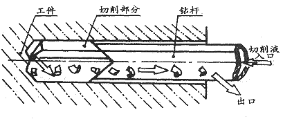 Figure 7 How the gun drill works |
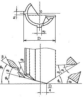 Figure 8 Main geometric parameters of the gun drill |
The connecting rod of 2V-6/8 air compressor produced by a factory is shown in Figure 1. The material is 45 steel, hardness HRC28~32, the two bolt holes have a dimensional accuracy of H8, the surface roughness is Ra1.6μm, and the parallelism tolerance of the two bolt holes is 0.15mm.
1 Process analysis
- Difficulties in deep hole drilling
- Difficulties in chip removal. When drilling deep holes, if the chips are not discharged in time, the chips may be blocked in the chip flutes, which will not only affect the machining accuracy, but may break the drill bit in severe cases.
- Poor cooling and lubrication. The drill bit works under semi-closed conditions, the cutting fluid is difficult to inject into the cutting zone, and the friction between the chip, the tool and the workpiece is very large, especially in the case of continuous cutting for a long time, a large amount of high temperature chips and a high cutting temperature are generated. Effective measures must be taken to ensure that the drill bit is cooled and lubricated, which would otherwise exacerbate bit wear.
- Poor orientation. Due to the deep hole and the slenderness of the tool, the strength and rigidity of the drill bit are poor, and it is easy to deflect and generate vibration during processing. In order to ensure the straightness and surface roughness of the drill hole and prevent the drill bit from breaking, the guiding problem must be solved.
- Process analysis
- The advantages of using the vibratory gun drilling process are: reliable process, high processing quality, high efficiency and low cost. The disadvantages are: long design and manufacturing cycle, large investment, and high requirements on equipment accuracy. However, with the improvement of the technical level of the manufacturing industry, the shortcomings of high precision on equipment have been insufficient. This solution is generally suitable for high-volume production.
- The traditional process scheme of drilling one expansion and one reaming has the advantages of short design and manufacturing cycle, small investment, reliable process and stable quality. The disadvantages are: long process route, low efficiency and high working hours; therefore, the solution is generally suitable for small batch production.
The two bolt holes of the air compressor connecting rod are small and deep, the ratio of length to diameter is 6:1, and the precision is high. The problems in processing are:
In order to achieve the specified technical requirements for the manufacturing accuracy of the parts, it is necessary to solve the three problems described in 1.1. The two bolt holes can be processed in the following two ways.
2 drilling with a vibrating gun
The traditional process of drilling one hole and one reaming will not be repeated here. The following is a detailed description of the problems related to the hole machining of the vibrating gun drill.- Machine tool modification
- Gun drill structure features, geometric parameters and working principle
Choose a common lathe with high precision and speed, and attach a coolant supply system to it. The tool holder is removed, and the fixture is fixed on the horizontal carriage of the machine; the chip box is arranged on the left side of the slide box, the front end of the machine tool spindle is equipped with a gun drill bit, and the vibration source is installed on the front and rear sides of the machine tool spindle, and the coupling is installed. Installed behind the spindle and attached to the headstock. The overall layout is shown in Figure 2. When drilling, first start the motor, the oil pump presses the coolant into the inner hole of the gun through the high pressure oil tank and the hollow rod, and then the gun drill drives the gun to rotate at a high speed. The vibration source makes the gun drill rotate while rotating, and the workpiece is fed by the slide box. At this time, the high-pressure coolant is sprayed into the cutting area by the oil hole at the front end of the drill bit, and then the outer side of the gun is drilled together with the chip. The 120° V-shaped groove is discharged into the chip box. After drilling the first hole, the horizontal carriage moves laterally by 85 ± 0.01 mm and drills the second hole.
The structure of the coupling is shown in Fig. 3. The calibration ring 6 makes the tie rod 8 coaxial with the machine tool spindle 7, and the tightening ring 5 is connected by a left-hand thread, so that the tightening ring does not fall off when the spindle rotates forward. The fork 3 is mounted on the oil collecting tank 4 with a screw 2, and the sleeve does not rotate when the spindle rotates. The leaked cutting oil flows back to the tank by the return line 1.
The structure of the drill chuck and the vibration source is as shown in Fig. 4. The gun drill is installed in the collet 8 and the main shaft 7 is rotated by the shaft 7, the sliding shaft 2, and the drive shaft 1, and the drive disc 6 is tightly pressed by the spring 3. It rests on the vibrating wheel 4. The eccentric shaft 5 has an eccentricity of 0.1 mm. Due to the frictional force, the drive plate 6 performs regular axial vibration while rotating, thereby enabling the gun drill to achieve axial vibration while rotating. In order to ensure that the gun drill can reliably achieve axial vibration, the eccentricity of the two eccentric shafts should be strictly consistent, and the finishing of the two vibrating wheels should be completed in one clamping.
The structure of the chip box is shown in Figure 5. Due to the machining method of the tool rotation, a higher requirement is imposed on the machine tool spindle, and the coaxiality tolerance of the inner hole of the drill sleeve 4 and the machine tool spindle is 0.02 mm. For this purpose, the mounting holes of the drill sleeve 4 can be machined by self-boring. In order to make the drill pipe bend if the sealing device on the left side of the chip box does not form a fixed support for the drill pipe, a gap of 0.5 to 1.0 mm may be left between the drill pipe and the drill pipe. In order to prevent splashing of oil during processing, the gasket 1, the pressure cap 2, and the spacer 3 should be processed into a shape similar to the cross section of the shank. The cushioning action of the spring 5 prevents the vibration caused by the start of the slippery box.
The structure is shown in Figure 6, which consists of a drill, a drill pipe and a drill handle. The drill pipe is made of seamless steel pipe and the chip drain is rolled close to the drill bit. The outer diameter of the drill pipe is 0.5 to 1.0 mm smaller than the outer diameter of the drill to avoid friction with the hole wall and the drill sleeve. The drill bit is generally made of integral high-speed steel or cemented carbide. The drill with a diameter of more than 8 mm can be welded to the drill bit with a carbide insert.
When the gun drill is working, the high-pressure cutting fluid (3~10MP, the water pressure is larger, the pressure should be larger) is driven from the inner hole of the drill pipe, sent to the cutting zone for cooling lubrication, and the chip is flushed out from the chip drain. As shown in Figure 7.
The geometric parameters of the gun drill blade are shown in Figure 8. The determination of the outer angle Ø 1 , the inner angle Ø 2 and the position of the drill tip has a great influence on the drilling accuracy and chip formation, and is determined by the calculation of the radial cutting force. Inner and outer corners of the drill tip an appropriate mix, or approximately balanced so that the cutting forces can force direction toward the first guide strip is a 1, so that the gun drill maintain a good self-directed, cutting and extrusion orifice can be completed , to ensure the accuracy of the hole being machined, surface roughness and straightness.
3 Discussion on the mechanism of vibration drilling
- After the axial vibration is added, the cutting edge and the chip and the cutting surface are periodically connected and separated, and the cutting fluid is fogged due to the high vibration frequency, so that the cutting fluid can fully enter the cutting zone, the cutter, the chip and the machining. The coefficient of friction between the surfaces is greatly reduced. Thereby effectively reducing the generation of cutting heat.
- Due to the existence of vibration, the formation condition of the built-up edge is destroyed, the process of chip formation is controlled, chip breaking and chip removal are promoted, and the working condition of the bit is greatly improved, so that a good surface quality can be obtained.
- Reasonable determination of the outer angle Ø 1 of the drill bit, the size of the inner angle Ø 2 and the position of the drill tip enable the gun drill to be well guided, thereby ensuring the straightness of the hole to be machined. The squeezing action of the guide strip a 1 helps to improve the roughness of the hole surface.
4 Summary
The vibratory gun drill described in this paper is applied in the machining of the two bolt holes of the 2V-6/8 air compressor connecting rod produced by a factory. The surface roughness of the hole can reach Ra0.2μm in one pass, and the straightness of the hole Up to 0.05mm/m.
ICESUN vacuum glass can maintain the high vacuum degree of the glass cavity for a long time, and greatly reduce the failure phenomena such as performance attenuation in various harsh environments. The fulcrum in the glass room is placed automatically by the machine, and the building glass is clamped automatically with a vacuum degree of 10-4 Pa when vacuumizing. 12mm ICESUN tempered vacuum glass is much lighter than 20-50mm insulating glass, which has lower requirements for structural frame materials and hardware components, and reduces the cost of doors, windows and curtain walls by about 50%. The window with Safety Vacuum Glass is not easy to sag and deform, and the service life is longer. ICESUN Vacuum Glass For Buildings adopts low melting point technology, aerospace grade welded glass edge sealing, with the same expansion rate and no air leakage, all of which make our High-tech Vacuum Glass popular among building glass materials.

Long Life Vacuum Glass,Long Life Insulated Glass,Long-Life Vacuum Insulated Glass,Long Life Glass For Buildings
ICESUN VACUUM GLASS LTD. , https://www.icesunvacuumglass.com