Figure 4 Waveform output of normal spark discharge pulse and arc pulse <br> after photoelectric coupling
A——normal spark discharge pulse output, b——arc pulse output
During processing, the pulse voltage of the discharge poles is very high, ranging from several tens of volts to several hundred volts, and the voltage of the gap voltage must be pre-processed by the pre-processing circuit. The attenuated gap voltage is optically isolated, operationally amplified, and then input to the sampling circuit. Since from the safety point of view, one electrode of the EDM machine is grounded, and the ground line is in communication with the center line of the AC power source. In addition to the coupling of the space electromagnetic field, there is direct coupling of the ground line. The EDM discharge gap is not only a processing area, but also a strong source of high-frequency electromagnetic interference. Its frequency range is 10 to 60 MHz. The experiment proves that the system has the strongest interference in the maximum current finishing. In order to prevent A/D sampling from being interfered, the isolation between strong and weak current is achieved, and the isolation in the discharge gap state detection interface circuit adopts linear photoelectric isolation technology.
The purpose of the control is to maintain the spark discharge state as much as possible under stable processing. The discharge process is described as four basic states: normal spark discharge, stable arc discharge, short circuit, and open circuit. Timing records the time at which the discharge state occurs, that is, the percentage of time used to reflect these four states and their combinations:
No-load rate: Ψd=Σtd/Σtiîƒ 100%
Spark discharge rate: Ψe=Σte/Σtiîƒ 100%
Stable arc rate: Ψa=Σta/Σtiîƒ 100%
Short circuit rate: Ψs=Σts/Σtiîƒ 100%
In the formula ti - pulse width td - no-load time te - spark discharge time ta - stable arc time ts - short-circuit time, the four basic states only the normal spark discharge has the ability to etch, the rest of the erosion material effect. Therefore, the control objective is to maximize the spark discharge rate Ψe under the premise of stable processing. Since the discharge time is extremely short (10-7~10-3s), it is very difficult to sample the voltage waveform in a single pulse, and the practical significance is not great. Therefore, the ratio of the number of quantitative pulses to the number of normal spark discharges is used as the control servo reference voltage. The parameter determines the monitored input parameter as the number of spark discharges per unit pulse during stable processing.
4 Experimental device and working principle 4.1 Experimental equipment (1) DK7180 (HCD800ZK) large precision CNC EDM machine with MDVA-105K pulse power supply cabinet and MD-P5 expansion cabinet;
(2) PC-2000 series PC/386/486/586 dedicated AD card PS-2117;
(3) The discharge gap detection voltage dividing interface circuit;
(4) Discharge gap state discrimination and logic circuit;
(5) Counting and interface circuit with PC.
4.2 Working principle of interface circuit (1) Discharge gap detection The voltage divider interface circuit separates the machine power system from the digital system.
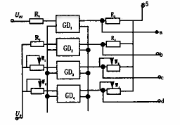
(2) The state detection circuit is based on the characteristics of the voltage of various state components of the discharge pulse. After the interface circuit is completed, data acquisition starts, including the synchronous equal-width trigger pulse Up2 of the pulse power supply to the gap, and the discharge gap voltage U0 after the interface circuit processing (see FIG. 5). In the figure, the resistors R1, R2, R3, and R4 are selected to have appropriate values ​​to enable the photocouplers GD1 and GD2 to operate in both off and saturation states. Under the action of the shunts W1, W2, W3, and W4, the input and output relationships of the photocouplers GD3 and GD4 have linear amplification characteristics in a certain voltage range. The output result is: 1 internal synchronous equal-width trigger signal a of the inverting power supply pulse (used as a source pulse for the rectangular timing window and external interrupt read and clear); 2 when the R1 input is low, the high level signal is output. b (short circuit signal); 3 output normal spark discharge cut-off voltage or stable arc discharge saturation voltage signal c; 4 high-level no-load (open circuit) signal d (here a reference level Uref2 is required).

Figure 5 Schematic diagram of sampling, optocoupler and partial amplification circuits
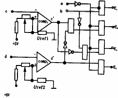
Therefore, according to the different high and low levels of the a, b, c, and d terminals, different discharge states with significant differences are obtained. We only need to set the reference levels Uref1, Uref2, and obtain the state components through the combination of comparator comp1 and comp2 logic circuit: short circuit signal E1, normal spark discharge E2, stable arc discharge E3, open circuit discharge E4 (see Figure 6 for the principle).

Figure 6 State Discrimination Logic Schematic
(3) High frequency counting and PC interface
In fact, after the processing of the previous circuit, we obtained the internal pulse trigger signal a of the power pulse, and used these signals to act on the counter to complete the separate counting of E1, E2, E3, and E4. Considering the operation of the microcomputer control system and the time loss of the terminal input and output, the signal a is divided by two and divided by four to obtain a1, a2, a, a1, a2 and the rectangular pulse window E, E and E1 respectively. The combination of E2, E3, and E4 obtains the counter strobe signals E1, E2, E3, and E4 (ie, the sampling period during the experiment is equal to the sum of the four discharge pulse periods). This part is implemented by software in the initial stage of the experiment.
6 Summary
The purpose of this experiment is to collect and detect the state of the discharge gap in real time online. In particular, the online difference between normal spark discharge and stable arc is detected. The processing after data collection is completely solved by the program. The program is written in C, so it brings a problem that cannot be ignored - there is a high time loss. It is recommended to use hardware in the future work, such as applying the programmable logic gate array device EPLD ATV2500 for logic operation and writing the program in assembly language, which will greatly speed up the processing speed of the software, and even collect accurate time of various discharge gap state delays. . After the whole process including the discharge gap interface circuit, state identification, counting and PC interface technology mature, consider integrating them into an EDM intelligent control card with integrated circuit boards, and directly perform analog and digital mode on the ISA bus slot of the PC. Conversion provides hardware support for intelligent control in EDM applications.
This paper proposes to determine the input parameters of the monitoring as the number of spark discharges per unit pulse during stable processing, and further tests are needed to verify its feasibility. However, it proposes a new attempt for state detection of EDM cavity processing.
The experimental device described in this paper is used to collect the data of the gap voltage in the EDM process in real time. It only needs to make software to perform real-time data processing and online control. Moreover, this experiment introduces IPC machine as the hardware platform for EDM processing monitoring and control, which not only can easily solve the man-machine interface problem, but also directly optimizes the CAD/CAM software for the data system. More importantly, it is possible to simulate on the microcomputer. The processing is processed and controlled in real time.
Previous page
25cm print pvc panel pvc ceiling
PVC Panel,PVC Ceiling,PVC Wall Panel
Goolee Decoration Material Co., Ltd. , http://www.jxpucolumn.com